Loudspeaker column design, built and tested as proof-of-concept
demonstration by Drew Daniels, Senior Technical Staff member of
Walt Disney Imagineering R&D department and electroacoustical
consultant to the Walt Disney Company, February-March of 1990.
Loudspeaker system component complement:
(4) 2242H subwoofers (2.1% conversion efficiency each or 8.4% in tandem)
(4) 2227H high-efficiency 15" woofers (one pair each side, about 17% efficient each pair)
(2) 2123H high-efficiency 10" midrange (3.5% efficient each)
(2) 2382A horn with 2450H compression driver (30% efficient each)
Efficiency or "conversion efficiency" is defined here
as the ratio-expressed as a percent-of the acoustical output obtained
for a given electrical input. Thus a transducer that delivers
5 acoustical watts to the air when fed a 100-watt electrical input
signal is said to be "5% efficient."
In case you're wondering if the poor 10" mid with its mere
3.5% efficiency, can keep up with the horn, rest assured I needed
10 dB of attenuation on the mid to get flat frequency response.
For amplification, I used two BGW SPA-3 triamplifiers. BGW was
happy to set up the triamplifiers to provide high-pass filtering
for the two 15's at 80 Hz, band pass for the 10" midrange
from 300 Hz to 1200 Hz, and band-pass and horn EQ filtering with
the lower end of the high frequency band at 1200 Hz. The crossover
slopes are Linkwitz-Riley type 24 dB/octave.¹ The amplifier's
input section also includes switched attenuation and built-in
signal delay to adjust the acoustic time of arrival for acoustically
aligning the cones and compression driver. Although the amplifiers
are each only 5.25 inches of rack space, they each produce up
to a total output of 1000 watts, providing 600 watts for each
pair of fifteen's, 200 watts for the mid and 200 watts for the
horn. This represents an average of around 30 dB of headroom
above normal living room listening levels, which generally range
in milliwatts for these speakers. Even though this
much headroom and power seem to be overkill, I assure you that
is not the case. I include here a table from my Audio Engineering
Society workshop on basic audio-it includes the results of about
130 hours of measurements I did of live and recorded material
using a $7500 Brüel & Kjær true-RMS voltmeter and
a $40,000 Brüel & Kjær audio analyzer to record
the peak-to-average power ratio of various signals. (1997 note:
these are no longer available except on special order. I recommend
using four solid-state amps of your choice-my choice is Adcom-and
building a 48 dB/octave (8th order) Linkwitz-Riley
crossover).
| SOURCE MATERIAL | CREST FACTOR |
| ROCK MUSIC | 10 dB |
| HORNS (legato notes) | 10 dB |
| REEDS (legato notes) | 12 dB |
| STRINGS (bowed) | 15 dB |
| SPEECH | 20 dB |
| PIANO | 30 dB |
| POP MUSIC | 40 dB |
| STRINGS (plucked) | 40 dB |
| DRUMS | 40 dB |
| ORCHESTRAL MUSIC | 50 dB |
| INDIVIDUAL PERCUSSION INSTRUMENTS | 60 dB |
| GENERAL HIGH-FIDELITY REPRODUCTION | 60 dB |
¹ Linkwitz-Riley 24 dB per octave (fourth-order)
or 48 dB per octave (eighth-order) crossover filter slopes produce
flat acoustic energy summation through the crossover frequency
region.
The BGW SPA-3 turned out to be the elegant and simple alternative
to a large rack of gear. Having done similar projects many times
in the past, I can honestly say I would not go back to the racks
and cabling and connectors and ground-loop chasing always necessary
as long as the SPA-3 is available to eliminate all the little
gremlins that tend to pop up when one builds up complex systems.
Note to builders: I don't recommend trying to build passive crossovers
for these units. Acoustic time-of-arrival delay of sufficient
time is not practical with passive devices and system performance
really suffers without it. Additionally, to obtain anywhere near
the performance of the tri-amped system using coils, caps, power
resistors and such, the crossover would be far more expensive
than a pair of SPA-3's and would probably weigh somewhere in the
neighborhood of 100 pounds-because of all the huge coils.
There have been many questions in the letters I've received about
doing this project some other way, with modifications, with different
components etc., perhaps to accommodate someone's favorite component
or fit some particular space or budget. I cannot address these
questions individually without addressing the particular goal
of the individual asking. I can do this-it is in fact, my livelihood-I
will be happy to design a custom system for you, but be aware
that this must be done on a consulting time basis. This project
however, is what it is, and as such, it pleased all the audio
golden ears at Disney enough that they insisted on using my lab
pair for the yearly Halloween show with an audience of 2500 people
spread over an outdoor area covering 235 degrees, as well as company
meetings with Eisner and Wells in huge tents with thousands of
people in the audience. This with a sizable company inventory
of all manner of THX-rated large theater systems, rock-concert
boxes form various manufacturers, etc.
THE MAGIC HORN FIX
There are some tricks that are essential for eliminating horn
"honk." The first is to use the cone driver placed
just below the horn, all the way up to a frequency where it begins
to "beam" due to the relationship of sound wavelength
and cone diameter. At a frequency where the resulting Q-factor
(directivity) of the cone matches that of the horn, the transition
from cone to horn will be smooth, and not abrupt-as it can be
in systems where the cone is too large and the horn is too small.
If this condition is met, and the frequency response of the cone
is good well beyond the frequency up to which it is used (a well-behaved
upper end rolloff), then the horn will enjoy a seamless transition
from the cone and will not honk, assuming its frequency response
is good and uniform over its output angle. This latter condition
is referred to as being "power-flat" and is very important
to the transparent operation of the speaker system in rooms, with
their concomitant acoustic implications. If the speaker system
is power flat, the sound in the room will be as good as that particular
room will allow it to be.
THE MIDRANGE
The midrange driver must be a cone, unless you live in a theater
and don't mind a 4-foot high horn (I crossed my mid at 300 Hz
into the woofers). As it turns out a mid cone supplying 300 Hz
to 1200 Hz gives the proper effortlessness with very little power,
and thus has extremely small cone excursions and low distortion.
As I mentioned earlier, I had to trim the 2123H mid cone back
10 dB on the amp's gain control to get the response through the
band flat. The power absorbed by the mid cone driver amounts
to milliwatts most of the time, which helps to hold harmonic distortion
to very low levels, typically well below 1% THD up to dangerously
loud volume.
I experimented with a dozen midrange drivers before I was confident
that the 2123H with its high efficiency and limited excursion
linearity would produce sufficiently low distortion. It is a
wonderfully transparent driver and a large part of the reason
this speaker system sounds like listening to live music rather
than loudspeakers. Note: as of 1995, JBL is manufacturing
a new even higher power 10" driver called the 2012H. If
you can obtain 2012H's, performance will increase even further.
The driver is mounted on the baffle as close to the horn as I
could get it with my inexpensive mid chamber geometry. You could
do better if you are willing to cut the shape of the mid driver's
frame into the lower lip of the horn and snug the mid frame up
into the cutout and, of course, figure out a mid chamber arrangement
that would clear the horn and driver behind the baffle, but this
is not measurably better than just a touching fit.
The enclosure for the mid cone consists of a 10-inch diameter
concrete casting tube made of plasticized paper. Such tubes are
made by Burke Tube and Sonotube and no doubt many
other regional paper products manufacturers. The tube is mounted
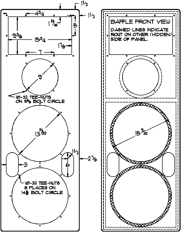
to the baffle by gluing into a counter-bored shoulder cut-out,
routed in the back of the baffle around the mounting hole. The
tube is about 12 inches long (deep), it is filled completely but
loosely with a "jelly roll" of unbacked fiberglass
house insulation cut from a roll about 4 feet long. The back
end of the tube is sealed air-tight with a disc of 1-inch thick
medium density fiber board-the same material used to build the
rest of the box.
Please, even if you hate handling fiberglass, don't substitute
other absorbing materials for it. Fiberglass is unique in its
physical properties and substitutes will not work as well. Just
get some long heavy rubber gloves to handle the stuff, and shower
off with cool or cold water when you're done.
One letter I received inquired
about using the JBL three-inch throat midrange compression driver
and horn. The horn itself is 44" wide by 42" high and
with the driver attached, is 42" deep and weighs 82 pounds.
The letter also asked about horn-loading the two 2227 cone drivers
for greater efficiency. Let me explain why I chose the geometry
I did, so that those of you inclined to even higher efficiency
can decide how to proceed from an informed set of criteria: First,
one of my design goals was the use of the typically small space
behind the perforated theater screens in the new smaller multi-cinema
complexes being built around the country and in Disney attractions
that have such screen spaces. Even at Disney Imagineering, it
would have been impossible to argue successfully for the space
behind the screens required for horn loaded systems, and in fact,
this column design (once tested and listened to) proved that horn-loaded
systems were not necessary to play even the loudest ear-splitting
explosion effects in theaters of 200 or 300 seats. Second is
the issue of acoustic impedance. Simplistically,
acoustic impedance is the ratio of radiation resistance to the
acoustical load. Radiation resistance varies with the size of
the acoustical aperture (source size) and the acoustical load
is the air in the room in which the source is operating. The
source drives the load, and so if we wish to avoid transmission
line conditions where we must match the source and load to obtain
proper power transfer and flat frequency response, we must provide
a source of low acoustic impedance (small source size) so that
the source output is sufficiently robust to essentially ignore
the load conditions. What we lose doing this is some efficiency
and sound pressure level capability; what we gain is flatter frequency
response and freedom from such effects as the deterioration of
performance when we move furniture around or close or open a door
or window. The real bottom line, however, may be that this little
column is simply more practical perhaps, than some other designs.
THE WOOFERS
The 2227 fifteen-inch cone driver should be thought of as a low-midrange-not
really a woofer. Yes it's a big driver with a big voice coil.
In fact, I use two of them in my bass guitar rig, but its QTS
and moving mass are so low that when you put it through Thiele-Small
calculations and plot curves on a computer as I did countless
times, the device ends up looking more like a midrange itself.
To be accurate, the Keele exponent-corrected program I use (because
it gives me systems that measure the same as the model predictions)
calls for about 1.5 cubic feet per driver, tuned to about 85 Hz-not
exactly organ pedals. I ended up opting for a slight over-damping
of two units in a 3 cubic foot volume tuned to 80 Hz. Even so,
the unassisted output of the box is flat to 65 Hz and droops only
slightly at 40 Hz, in the middle of a 40,000 cubic foot room (my
test lab at Imagineering R&D).
Be sure the high-pass filter on the amplifier driving the two
2227H's is set to 80 Hz and rolls off at a rate of at least 18
dB per octave. The 2227H drivers are high-efficiency, limited
linear excursion devices (in fact, they are one of the highest
efficiency cone drivers made anywhere). The crossover frequency
of 80 Hz is the design target to limit cone excursion and produce
a good transition to the subwoofers.
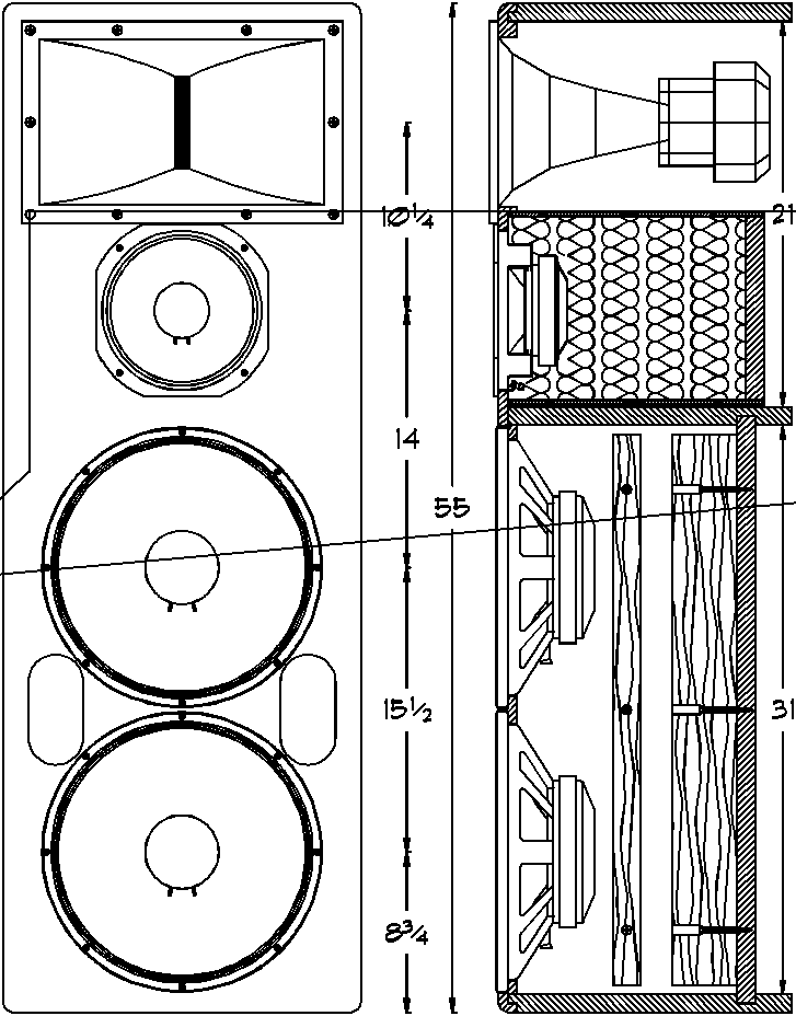
The enclosure is built as rigid and non-resonant as possible and
then lined with fiberglass over the entire interior surface area,
except around the ports where air turbulence might tear off pieces
of fiberglass and spray them around. The woofer portion of the
enclosure is the only real structure. The midrange tube is extremely
rigid and exceptionally non-resonant. My goal in designing the
woofer section was to minimize spurious panel-vibration and acoustic
output-within reason. There is more panel output, in fact, from
the thick, ribbed metal back cover of the compression driver.
I used four two-by-fours for bracing inside the woofer compartment.
These were counter-drilled for wood screws and glued with aliphatic
resin glue, on-edge, to the compartment panel interior surfaces.
I tried to space the braces at random-so that no two unbraced
panel areas were the same size-thus randomizing panel section
resonances. I also glued the two cutout discs from the woofer
holes to the outside of the back panels to make the total panel
thickness 2 inches, plus braces!
SETTING UP THE SYSTEM
This can be tricky. I used a TEF analyzer and a $40,000 1/24th-octave Brüel & Kjær real-time analyzer and intensity probe set of phase-matched microphones (another $14,000). First, I did energy-time measurements to set the delays in the amplifier. This proved to be difficult, since I had to take distance ranging measurements of each driver separately to make sure I was looking at arrival times from the intended measurement object. After I got the delays set, I checked frequency response the best I could in the space available, then resorted to the real-time analyzer. Be aware that the frequency responses you get with these two methods are very different because TEF windows its measurements to try to exclude reflections and examine only direct sound from the source, while real-time analysis includes all returning room energy information along with that from the speaker. I like a balance of both measurement methods, because one lets you fine tune the energy output of the speaker, and the other lets you adjust large trends like the general "too-bright" high end you will likely notice if you try to obtain flat output to 20 kHz from the direct-sound readings of a truly power-flat or "constant-directivity" horn. Such horns produce more high frequency energy in the first place because they distribute the energy over a larger angle, that is to say, if one equalizes such a horn for flat response, then more high frequency energy will be pumped into the listening space than would be the case for other types of horns. Most people are not used to listening to power-flat top-end, and will find it too brassy. Only minimal-miked big-band recordings will sound right with the system adjusted this way.
For your playback system head end, I recommend that you use an
extremely low-noise preamp with simple Baxendall type "tone
controls." The bass and treble turnover frequencies are
a matter of taste, but 100 Hz and 10 kHz or 200 Hz and 5 kHz seems
to work well to adjust this system to music on recordings. To
my ear, parametric equalization is less pleasing and is certainly
prone to putting more phase aberrations in more audible frequency
ranges than are simple tone controls. One-third octave "graphic"
equalizers are completely useless for high fidelity use and one-octave
units are even worse-avoid these. They introduce horrendous phase
shift problems of their own, and if not properly analyzed with
the system they are driving, will virtually always degrade performance.
Begin adjusting with the amp master gains set low, and turn the
preamp all the way up. Slowly advance the amp gains until you
can achieve proper balance and slightly louder than necessary
output. This will ensure that you will have the least possible
amplifier hiss from the speakers. Amplifier hiss is a phenomenon
that rarely troubles owners of low-efficiency speakers, but these
monsters are efficient enough to make the transistor junction
noise of poorly designed amplifiers quite audible.
If any of you reading this decide to build this system, it will
cost around $10,000 including amps and all. If you get that serious,
if you are rich and adventurous and don't care what stereo salesmen
think, you are the type of person who would really enjoy this
system.
SUBWOOFERS
The Subwoofers should generally occupy the space between your
main speaker systems. The reason for this preferred location
is the so-called propagation delay of low frequency sound from
the sub units.
All loudspeakers are natural electromechanical filters and as
such, they produce a delay of some size between their input signal
and their acoustical output response-there is no exception to
the natural laws that cause this type of delay-despite what commercial
manufacturers put on their literature.
In more technical terms, the amount of delay depends on the filter
bandwidth and the amount of attendant phase shift inherent in
the filter's band-limit or envelope shape and other characteristics.
For example, a simple single-order or "single-pole"
filter produces 90 degrees of phase shift at the frequency, where
the signal passes through the half-power (-3 dB) frequency point.
Thus a subwoofer whose high-pass characteristic is a single pole
filter will exhibit a 6 dB per octave rolloff below its operating
band. If we use a sealed-box with a 30 Hz lower band limit defined
by the -3 dB or half power point, then we will have 90 degrees
of phase shift or a delay of 8.3 milliseconds at 30 Hz. This
delay is equivalent to roughly 9 feet of sound travel through
air.
At the crossover frequency of 80 Hz we are imposing on this system,
sound waves are 14.1 feet long. We will want to know what order
our crossover will be. We will assume the subwoofer upper band
limit is way beyond 80 Hz and will not add significant phase shift
to the crossover, (in fact the 2242H driver described could be
used as the low end of a three-way system up to 300-400 Hz with
no special consideration except that its conversion efficiency
is low). For the sake of example, I will use the common 18 dB/octave
crossover slope and calculate the position correction estimate
needed. First, each 6 dB/octave forms what we referred to as
a "pole" for the calculation. Three poles gives us
270 degrees of phase shift or three-quarters of a sound wave at
our 80 Hz crossover frequency. Three fourths of 14.1 works out
to be 10.6 feet.
Fortunately for us, there is also delay in the column's low-frequency
output due to the high-pass function and the built-in delays in
the amplifier we have adjusted to get our acoustical alignment
between cones and horn. This means we will not have to place the
subwoofers 10.6 feet forward of the columns. In fact, because
of the ear's forgiveness, you'll find there's a "window"
of space for physical placement that allows a good deal of flexibility
in setting the speakers into your listening space.
WHAT YOU HAVE WHEN YOU'RE DONE
These loudspeaker systems could easily be used behind a perforated
movie screen, providing sound to an audience of hundreds of people
in a small movie theater (the original design intent).
They are also equally capable in a home listening room setting,
of causing you permanent hearing loss, and doing so quickly.
I have two tips for you and I urge you to pay heed:
First, play music at no more than realistic levels. I assume
that if you choose to build these things, you've done so because
you're interested in fidelity of the reproduced sound to the originally
recorded sound. You will get the best representation of the original
sound if you play the reproduction at the original sound level.
Playing too loud is as detrimental to fidelity as playing too
softly.
If you play predominantly rock music, there is no such thing as
an original sound level-since all the recorded material comes
out of a little electronic box or was derived by sticking a microphone
somewhere you would never purposely put your ears.
In either case, you need to keep a sound level meter handy. You
can get a perfectly adequate SLM at your local Radio Shack store
for around fifty bucks, and for your ears sake, don't ignore this
advice.
These speakers make so little distortion that you will be tempted
to believe that the 120 dB sound you are listening to is only
playing at 90 dB. This is not good. You will lose your
hearing. Don't let this happen.
If you find that the clean sound causes your favorite rock artist to be emasculated, you can go out and get an Aphex Aural Exciter to add distortion back in so that it sounds loud again. (Seriously)
Here's a "parts list" in case you get ambitious.
FOR THE COLUMNS:
(2) BGW model SPA-3 triamplifiers (contact the BGW factory to custom order).
(2) JBL 2450J compression drivers.
(4) JBL 2227H cone transducers.
(2) JBL 2382A horns.
(2) JBL 2123H cone transducers.
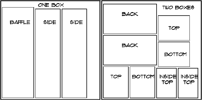
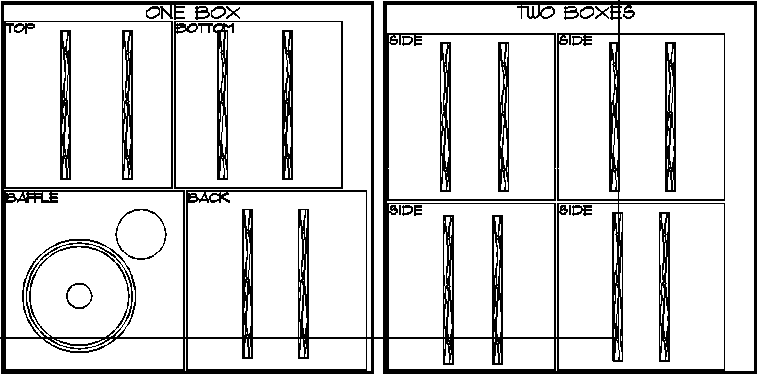
(3) Sheets, MDF (Medium
Density Fiberboard) 60" square 1" to cut parts for
two boxes.

(2) Six-position barrier terminal strips (8-32 screws or larger).
(1) Package, #10-14 spade lugs and professional crimper.
(1) Length, 12-gauge twisted pair wire to hook up transducers.
(1) Small box, 2" drywall screws.
(1) Large bottle (16 oz.) Aliphatic Resin wood glue.
(1) Quantity two-by-fours, to make eight 30" pieces.
(1) Concrete casting tube, 10" I.D. 3 feet.
(32) 10-32 2" Philips pan head machine screws.
(8) 10-32 1.5" Philips flat head machine screws.
(24) 1/4-20 2" black Philips flat head machine screws.
(40) 10-32 1/2" T-nuts.
(120) square feet of R-19 unbacked pink fiberglass (for columns and subwoofers).
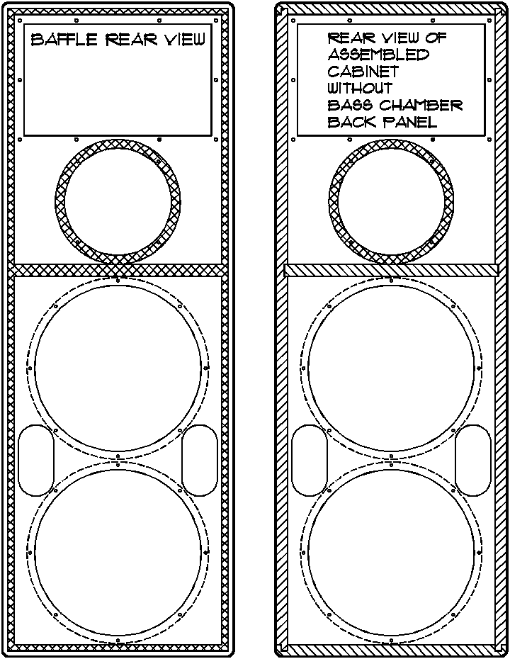
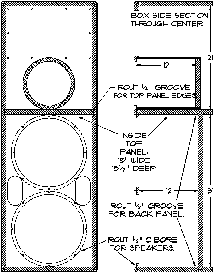
WOOFER CHAMBER BACK REMOVED
FOR THE SUBWOOFERS:
(4) JBL 2242H cone transducers.
(6) Sheets, MDF (Medium Density Fiberboard) 60" square 1" to cut parts for four boxes.
(1) Length, concrete casting tube, 8" I.D., to make four 15" long pieces.
(1) Quantity two-by-fours, to make forty 24" pieces.
(4) Two-position barrier terminal strips, (10-32).
(32) 10-32 2" Philips pan head machine screws.
(32) 10-32 deep T-nuts.
Cut four pieces of tube at 15"
length.
Rout baffle counter bore for tubes
to O.D. of tube, 1/2" deep in back of baffle.
Cut eight panels for baffles and backs,
29" square.
Cut eight panels for tops and bottoms,
29" 27"
Cut eight panels for sides, 27"
square.
Attach two pieces, two-by-four, 24"
long to each panel, screwed and glued on edge as for columns.1
Butt-join all pieces together using
cabinet clamps.
Line all five surfaces except the baffle,
completely with fiberglass. Take care to keep the fiberglass
away from the vent duct end or it may be sucked in and sprayed
into the room by the air turbulence at the inside end of the duct.
1 note: make
sure brace pieces on the different panels clear each other when
the box panels are assembled.
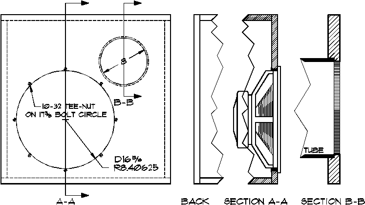
The Subwoofers pictured here, should generally occupy the space
between your main speaker systems. The reason for this preferred
location is the so-called propagation delay of low frequency sound
from the sub units.
All loudspeakers are natural electromechanical filters and as
such, they produce a delay of some size between their input signal
and their acoustical output response-there is no exception to
the natural laws that cause this type of delay-simply because
sound waves vary in size.
In more technical terms, the amount of delay depends on the distance
(in time) between the zero-crossing and the maximum pressure formed
in the air by loudspeaker diaphragms along with the filter bandwidth
and the amount of attendant phase shift inherent in the filter's
band-limit or envelope shape and other characteristics. For example,
a simple single-order or "single-pole" filter produces
90 degrees of phase shift at the frequency where the signal passes
through the half-power (-3 dB) frequency point. Thus a subwoofer
whose high-pass characteristic is a single pole filter will exhibit
a 6 dB per octave rolloff below its operating band. If we use
a sealed-box with a 30 Hz lower band limit defined by the -3 dB
or half power point, then we will have 90 degrees of phase shift
or a delay of 8.3 milliseconds at 30 Hz. This delay is equivalent
to roughly 9 feet of sound travel through air.
At the crossover frequency of 80 Hz we are imposing on this system,
sound waves are 14.1 feet long. We will want to know what order
our crossover will be. We will assume the subwoofer upper band
limit is way beyond 80 Hz and will not add significant phase shift
to the crossover, (in fact the 2242H driver described could be
used as the low end of a three-way system up to 300-400 Hz with
no special consideration). For the sake of example, I will use
the common 18 dB/octave crossover slope and calculate the position
correction guess needed. First, each 6 dB/octave forms what we
referred to as a "pole" for the calculation. Three
poles gives us 270 degrees of phase shift or three-quarters of
a sound wave at our 80 Hz crossover frequency. Three fourths
of 14.1 works out to be 10.6 feet.
Fortunately for us, there is also delay in the column's low-frequency
output due to the high-pass function and the built-in delays in
the amplifier we have adjusted to get our acoustical alignment
between cones and horn. This means we will not have to place the
subwoofers 10.6 feet forward of the columns. In fact, because
of the ear's forgiveness, you'll find there's a "window"
of space for physical placement that allows a good deal of flexibility
in setting the speakers into your listening space.
"NEAR-FIELD" SUBWOOFING
There is an alternative to the four expensive monster sub cubes,
but it takes some getting used to; both in terms of the concept
and the execution. Near-field subwoofers can be used near (directly
behind) the listening position. Placing the subs close to your
ears offers three advantages:
1. Smoother low-end frequency response, because of the direct-to-reflected
ratio of the sound you actually hear. Standing waves create huge
peaks and nulls in response depending on your room characteristics,
but if you can get really close to the sound source, your proximity
alone swamps out the peaks and nulls because of the lower the
output level of the subs required to compensate the inverse square
law distance losses. If you are listening to only (or mostly)
direct sound and not room reflections, then you will hear sound
as smooth as the loudspeaker can provide.
2. Since you're using less power (typically about a quarter as
much) you can get away with smaller devices-maybe one cube or
a custom box with a pair of cheap 12" subwoofer drivers inside.
You will have to ensure that the box itself produces good, flat
response, but even this is easier to get-and down to a lower frequency-when
you use a near-field arrangement.
3. Your neighbors and your family will appreciate not having their
teeth loosened by massive bass penetrating the entire house.
Bass carries the most because its long waves are so much harder
to absorb or bend. You've probably noticed (in L. A. we sure
do) how the cars with monster audio systems only seem to make
bass as they pass on the street outside. Bass carries like a
fog horn, and near-field subwoofers can reduce the amount of sound
energy you initially pump into the air.
Of course, careful balancing will have to be done to match levels
with the front loudspeakers, and you will need a good audio delay
line to delay the subwoofer signal between 5 and 50 milliseconds.
I recommend using something like a pair of Plye 12" subwoofer
drivers in a sealed box shaped something like a low boy table,
placed directly behind your couch. The box should be about 10
cubic feet internally, and it should be stuffed loosely but completely
full of R-30 fiberglass to ensure that it is over-damped. If
you're serious about the project, you should also get a 1/3rd
or a 1/6th-octave graphic equalizer to flatten out the box from
the listening position.
ADDENDA
Speaker cabling:
Prepare speaker cabling for the high frequency horns only
from multiple twisted pair Spectrastrip high-speed computer
data ribbon cable. You can parallel as many conductors as you
like to obtain the equivalent of a 14, 12 or 10 AWG. This method
produces the finest performance available from wire-of any kind,
at any price! You may also use pairs of single 10-gauge stranded
wires which you can twist using an electric drill motor. Twisting
conductors around each other places the current paths (and resulting
surrounding magnetic fields) closer to right angles to each other
which in turn reduces inductance-the main property of speaker
cabling that can cause a loss in high frequencies in the amp-cable-speaker
system. You can use any 10 or 12-gauge wire pairs for the mid
and lower frequency drivers or even as small as 16-gauge if cables
are short.
Terminate the three pairs of wires into a screw-terminal barrier
strip mounted on top or on the back of the woofer chamber. From
there, continue with the same wire to the amp. Place the amp
nearby (it happens to be the same width as the speaker cabinet)
and keep speaker cables short to minimize resistance and capacitance.
This is the best you can do to insure that wire is not playing
a degrading role in your audio system.
It is essential that good connections with low contact resistance
be made at each connection. Use of crimped lugs is recommended
if the certified crimp tool is used to install the lugs. High-cost
gold-plated hardware which offer good mechanical connections are
acceptable if they can be made to provide a low-resistance connection
to the wire itself, and may offer additional benefits in avoiding
contact "poisoning" due to the molecular migration of
dissimilar metals across the connection. Periodic checks of connections
will, in any case, avoid chemical connection problems.
This project is expensive enough already. Don't
listen to any hair-brained morons who may try to tell you "special"
speaker wire will make any difference. It's not true-it's only
mysticism. If there were any actual advantages, such wire would
have found its way into the engineering mainstream for large military
projects, and satellites where billions in research would surely
have revealed the benefits and resulted in at least some
documentation. PERCEIVED benefits are exactly that-perceived-as
a direct result of psychological inclination to rationalize and
justify the absurd expenditure of money for what amounts to nothing
more than prestige.
Lastly, if you're totally into perfection, I can highly recommend the Sigtech AEC 1000 Acoustic Environment Correction System. It is a serious engineering tool developed from the technology of radar image enhancement. The box (and a PC) measures and stores the total transfer function of the loudspeakers and the room, convolves huge DSP filters (2470 filter poles) from the stored measurement, and processes your audio at 250 million operations per second to produce corrections from up to four listening positions. You are left with smoother frequency response with a vastly closer match between left and right, and smooth phase response in the bargain since the correction is done in the time domain. No other device even comes close to the power this thing provides. You could turn one of your speakers toward the wall so that its output is reflected back to you later and with wider dispersion and added absorbtion, and the box is capable of correcting so thoroughly that the stereo image will be pulled right back to the center as if everything was normal! I used this thing at Disney to make Hi-Fi through tubes! And it worked!! It will cost you between $6500 and $8500 depending on whether you want the whole analysis system or are content to have an engineer set it up for you. For more information about the Sigtech, e-mail me at drewdaniels@worldnet.att.net.